simulating Metrigear Vector cadence extraction (pt 3: cadence accuracy)
Last time I simulated the Metrigear Vector cadence extraction using reasonable assumptions about vertical and longitudinal vibrations, and a quite arbitrary choice on differential vibrations (separate for the left and right pedal). The result looked fairly good, despite the fact my algorithm for extraction is just something I hacked together on my train commute, hardly a best case of what one could do. I'm not using all the information which is available. I'm not really using the transverse component of acceleration, for example.
But let's take a closer look at those numbers... I ran 10 simulations, and for each time, I calculated the error in the rpm from the ideal value (pre-noise). I calculated the root-means-squared of these errors, and plot them here versus the ideal cadence:
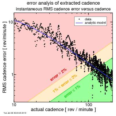
Cadence errors, in revolutions per minute, are plotted on the y-axis. Also plotted is a curve derived from a simple analytic model, based on the amplitude assumed for the differential noise. It's easy to see this simple model tracks fairly well: the differential noise (all that the analytic model considers) dominates. In the plot, the green zone represents a less than 1% error, while the red zone a more than 2% error. To hit a 1.5% accuracy target for power, certainly the cadence error, cadence being only part of the power calculation (the other being force), should be no more than 1%.
The result is this 1% target is hit only for relatively high cadences. Hmm....
Now recall when I was discussing this differential noise, I noted that the accelerometers themselves are capable of measuring acceleration to remarkable accuracy: well within the requirements of cadence measurement. So I suggested crank flex as a possible source of such "error". And I had to get rather pessimistic about crank flex to get the 0.25 g peak amplitude I'd assumed for the differential noise acceleration components.
But is crank flex "noise" or is it "signal"? That's complicated, really, If the crank flex means the pedal moves forward or backward in its motion, that's not noise: that's a real change in pedal rotation rate. We need to include that to get the correct answer for power. On the other hand, if the crank flex is radial (that is a relative change in the crank length), well, then that's clearly noise. We're using the acceleration in this direction as a proxy for rotation rate. Crank length fluctuations do not represent propulsive power.
I think it's safe to say the length of the cranks doesn't actually change much. However, it's possible that frame flex causes the povot point for the cranks to move around a bit. And if the povot point moves, that's similar to the crank length changing.
But back a second to that crank length question: in reality, with flexing cranks the L & R pedals are not necessarily rotating at the same rate. I average the L & R accelerations to get a single rotation rate. This will introduce a bit of an error. But it's not likely as big of an error as assuming all crank flex is "noise".
So the key question is what the magnitude is of this "noise" term? And that's not so easy to measure, because as I noted, some of the "noise" is actually signal: real differences in the rate of pedal rotation.
So I did the previous analysis again, but this time instead of being pessimistic, I was optimistic: I shut off the differential noise term. Now all that's left is the vertical and horizontal noise. These "leak in" to the error since the pedal orientation may not be known to perfection, so the averaging of the left & right components fails to perfectly eliminate road vibration and translational acceleration.
Here's the result, where I keep the analytic model used before to facilitate comparison:

Now noise is a lot less. Here the 1% target is hit down to around 50 rpm. And this result is only a few seconds after the pedals were re-oriented, so with more time to nail down the pedal orientation, it would improve.
It's tempting to reduce the influence of these noise terms by filtering, with more smoothing applied as the cadence drops. But just because the crank is rotating slowly doesn't mean that high-frequency components are no longer of interest. Road vibrations may cause the chain to oscillate, which causes fluctuations in the rate of crank rotation. So personally I'd not want to do any sort of cadence-dependent filtering. But if RPM is detected by radial acceleration, that may be prudent for low cadences, since this acceleration component is proportional to the square of the cadence and therfore diminishes rapidly.
An aside: whenever noise is a factor, the more information you can use, even if that information is redundent, helps accuracy. In this case, there's that transverse acceleration component. It doesn't give cadence directly, but does in theory give the rate of change of acceleration. That might be useful, but not without substantially complicating things. I'll leave that alone for now. I like simple: it's complex enough, especially for my train commute.
Next time I'll look at the orientation extraction accuracy.
But let's take a closer look at those numbers... I ran 10 simulations, and for each time, I calculated the error in the rpm from the ideal value (pre-noise). I calculated the root-means-squared of these errors, and plot them here versus the ideal cadence:
Cadence errors, in revolutions per minute, are plotted on the y-axis. Also plotted is a curve derived from a simple analytic model, based on the amplitude assumed for the differential noise. It's easy to see this simple model tracks fairly well: the differential noise (all that the analytic model considers) dominates. In the plot, the green zone represents a less than 1% error, while the red zone a more than 2% error. To hit a 1.5% accuracy target for power, certainly the cadence error, cadence being only part of the power calculation (the other being force), should be no more than 1%.
The result is this 1% target is hit only for relatively high cadences. Hmm....
Now recall when I was discussing this differential noise, I noted that the accelerometers themselves are capable of measuring acceleration to remarkable accuracy: well within the requirements of cadence measurement. So I suggested crank flex as a possible source of such "error". And I had to get rather pessimistic about crank flex to get the 0.25 g peak amplitude I'd assumed for the differential noise acceleration components.
But is crank flex "noise" or is it "signal"? That's complicated, really, If the crank flex means the pedal moves forward or backward in its motion, that's not noise: that's a real change in pedal rotation rate. We need to include that to get the correct answer for power. On the other hand, if the crank flex is radial (that is a relative change in the crank length), well, then that's clearly noise. We're using the acceleration in this direction as a proxy for rotation rate. Crank length fluctuations do not represent propulsive power.
I think it's safe to say the length of the cranks doesn't actually change much. However, it's possible that frame flex causes the povot point for the cranks to move around a bit. And if the povot point moves, that's similar to the crank length changing.
But back a second to that crank length question: in reality, with flexing cranks the L & R pedals are not necessarily rotating at the same rate. I average the L & R accelerations to get a single rotation rate. This will introduce a bit of an error. But it's not likely as big of an error as assuming all crank flex is "noise".
So the key question is what the magnitude is of this "noise" term? And that's not so easy to measure, because as I noted, some of the "noise" is actually signal: real differences in the rate of pedal rotation.
So I did the previous analysis again, but this time instead of being pessimistic, I was optimistic: I shut off the differential noise term. Now all that's left is the vertical and horizontal noise. These "leak in" to the error since the pedal orientation may not be known to perfection, so the averaging of the left & right components fails to perfectly eliminate road vibration and translational acceleration.
Here's the result, where I keep the analytic model used before to facilitate comparison:
Now noise is a lot less. Here the 1% target is hit down to around 50 rpm. And this result is only a few seconds after the pedals were re-oriented, so with more time to nail down the pedal orientation, it would improve.
It's tempting to reduce the influence of these noise terms by filtering, with more smoothing applied as the cadence drops. But just because the crank is rotating slowly doesn't mean that high-frequency components are no longer of interest. Road vibrations may cause the chain to oscillate, which causes fluctuations in the rate of crank rotation. So personally I'd not want to do any sort of cadence-dependent filtering. But if RPM is detected by radial acceleration, that may be prudent for low cadences, since this acceleration component is proportional to the square of the cadence and therfore diminishes rapidly.
An aside: whenever noise is a factor, the more information you can use, even if that information is redundent, helps accuracy. In this case, there's that transverse acceleration component. It doesn't give cadence directly, but does in theory give the rate of change of acceleration. That might be useful, but not without substantially complicating things. I'll leave that alone for now. I like simple: it's complex enough, especially for my train commute.
Next time I'll look at the orientation extraction accuracy.


Comments