Metrigear Vector Pt 8: Pedal Speed (2)
In the last post I discussed some data Metrigear presented on their blog showing accelerations measured at the pedal spindle, decomposed into radial and tangential components. I wanted to step back and discuss the derivation of power from pedal speed. Okay, to be honest I'd prepared this blog post and skipped past it to post the one responding to Metrigear's data. So I'm a bit out of sequence: this one was mostly written before the Metrigear post.
Mechanical power is the component of force in a particular direction times the speed in that direction at which the power is being applied. We've already worked out the force components, and determined the direction of propulsive power, so all that remains is to determine the speed along that direction. So all that remains is to determine the speed along that direction.
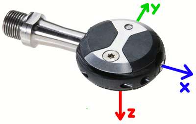
We'll assume again the coordinates of the right pedal:

Axes for right pedal
The propulsive force is applied in the x direction, which is a fixed direction in the coordinates of the spindle. So we need to determine the rate at which the pedal is rotating in that direction.
If the bike is in a zero-gravity inertial frame, for example at rest on a trainer in a space station, then the solution is easy: there is only one component of acceleration, which is that associated with the pedal rotating. From the schematic, the pedal is moving in the +z direction, orbiting about an axis of rotation in the x direction, and is therefore accelerating in the -y direction. A way to remember this relationship is that all planets accelerate toward the sun, which attracts them gravity, and yet their trajectory is roughly circular about the sun, so a circular motion has an acceleration toward the center of rotation. In this case, the magnitude of that acceleration is:
aω = ω² L,
where ω is the rate of rotation (radians per unit time) and L is the crank length. Note aω differs slightly from the aorbital used in the the last post as they differ in the reference. aω is referenced to the bicycle frame, where aorbital was referenced to inertial space. More on that in a bit...
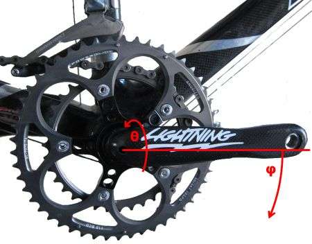
Of course the Vector isn't designed just for stationary trainers in space stations. There's other forces at play. There's gravity, for example. Then there's the acceleration of the bike moving forward. For simplicity, I'll make what seems the reasonable assumption that the spindle is always perpendicular to the direction of forward motion. To consider more components of bicycle acceleration, more coordinates are needed. These are defined in the following diagram:

Angular coordinates
Two coordinates are defined here: φ, which is the angle of the crank arm relative to the bike frame horizontal, and θ, which is the "roll angle" of the bike relative to the pull of gravity.
An important point: why is φ relative to the bike frame and not the pull of gravity? Propulsion is propulsion is proportional to the rate of change of φ times applied torque. Now suppose that φ is changing at a steady rate, but the effective grade of the road is also changing. Let's define the angle of the road (and therefore of the bike) relative to the horizontal as defined as the plane perpendicular to the pull of gravity as φbike. Then does the applied propulsion depend on whether φbike is increasing or decreasing? The answer is clearly not, since what matters is the speed with which the chain is driving the rear cassette, and the relevant chain speed is the rate of rotation of the crank relative to the bicycle frame. If the whole bike is rotating because the road grade is changing, and a force is applied to the pedal, but the pedal is locked into position somehow, no work is done even though there is a torque being applied and being moved through an angle relative to the direction of gravity. The key is the pedal is not being moved through an angle relative to the the bike frame. Of course the laws of physics are generally defined with respect to inertial reference frames. But the key again is Newton's Third Law, which suggests in the locked pedal example the measured torque is being balanced by an unmeasured one. That unmeasured torque in this case is through the wheels: the wheels are being pushed by the earth in a way which cancels out the propulsive torque of the pedals moving through an angle in inertial space. The component of torque not canceled by the wheels is that due to motion of the crank relative to the bike frame, as we've defined.
So with that long-winded discussion, we can define applied power:
Applied power ≡ P = Fz ω,
ω = dφ / dt.
All that remains is to measure ω for real-world situations. If we can derive the rotational acceleration aω we can derive
ω = √(aω / L)
We then need to extract aω.
I discussed last time how to perhaps estimate ω by averaging radial accelerations for the left and right pedal spindle. A caveat there is my discussion about the relevant rotation being relative to the bike frame. Spin the entire bike, and the pedals will spin with the bike, and yet no propulsion is being applied to the chain. Nevertheless, this is a relatively small error, since the pedals typically change their angle a lot faster than the bicycle does. Were one to extract rate of crank rotation from an optical sensor between the crank arms and the bottom bracket, the rotation would be relative to the bicycle frame and not due to inertial space. This would be better, but of course adding an additional cadence sensor adds mass, cost, and complexity for dubious benefit.
Next I'll try to guess how to do it for one pedal spindle. It's not obvious, however, I admit. Maybe I'll stall for time by returning to a discussion of climbing power, or maybe discuss the joys of endoscopy. But that's off topic.
Mechanical power is the component of force in a particular direction times the speed in that direction at which the power is being applied. We've already worked out the force components, and determined the direction of propulsive power, so all that remains is to determine the speed along that direction. So all that remains is to determine the speed along that direction.
We'll assume again the coordinates of the right pedal:

Axes for right pedal
The propulsive force is applied in the x direction, which is a fixed direction in the coordinates of the spindle. So we need to determine the rate at which the pedal is rotating in that direction.
If the bike is in a zero-gravity inertial frame, for example at rest on a trainer in a space station, then the solution is easy: there is only one component of acceleration, which is that associated with the pedal rotating. From the schematic, the pedal is moving in the +z direction, orbiting about an axis of rotation in the x direction, and is therefore accelerating in the -y direction. A way to remember this relationship is that all planets accelerate toward the sun, which attracts them gravity, and yet their trajectory is roughly circular about the sun, so a circular motion has an acceleration toward the center of rotation. In this case, the magnitude of that acceleration is:
aω = ω² L,
where ω is the rate of rotation (radians per unit time) and L is the crank length. Note aω differs slightly from the aorbital used in the the last post as they differ in the reference. aω is referenced to the bicycle frame, where aorbital was referenced to inertial space. More on that in a bit...
Of course the Vector isn't designed just for stationary trainers in space stations. There's other forces at play. There's gravity, for example. Then there's the acceleration of the bike moving forward. For simplicity, I'll make what seems the reasonable assumption that the spindle is always perpendicular to the direction of forward motion. To consider more components of bicycle acceleration, more coordinates are needed. These are defined in the following diagram:

Angular coordinates
Two coordinates are defined here: φ, which is the angle of the crank arm relative to the bike frame horizontal, and θ, which is the "roll angle" of the bike relative to the pull of gravity.
An important point: why is φ relative to the bike frame and not the pull of gravity? Propulsion is propulsion is proportional to the rate of change of φ times applied torque. Now suppose that φ is changing at a steady rate, but the effective grade of the road is also changing. Let's define the angle of the road (and therefore of the bike) relative to the horizontal as defined as the plane perpendicular to the pull of gravity as φbike. Then does the applied propulsion depend on whether φbike is increasing or decreasing? The answer is clearly not, since what matters is the speed with which the chain is driving the rear cassette, and the relevant chain speed is the rate of rotation of the crank relative to the bicycle frame. If the whole bike is rotating because the road grade is changing, and a force is applied to the pedal, but the pedal is locked into position somehow, no work is done even though there is a torque being applied and being moved through an angle relative to the direction of gravity. The key is the pedal is not being moved through an angle relative to the the bike frame. Of course the laws of physics are generally defined with respect to inertial reference frames. But the key again is Newton's Third Law, which suggests in the locked pedal example the measured torque is being balanced by an unmeasured one. That unmeasured torque in this case is through the wheels: the wheels are being pushed by the earth in a way which cancels out the propulsive torque of the pedals moving through an angle in inertial space. The component of torque not canceled by the wheels is that due to motion of the crank relative to the bike frame, as we've defined.
So with that long-winded discussion, we can define applied power:
Applied power ≡ P = Fz ω,
ω = dφ / dt.
All that remains is to measure ω for real-world situations. If we can derive the rotational acceleration aω we can derive
ω = √(aω / L)
We then need to extract aω.
I discussed last time how to perhaps estimate ω by averaging radial accelerations for the left and right pedal spindle. A caveat there is my discussion about the relevant rotation being relative to the bike frame. Spin the entire bike, and the pedals will spin with the bike, and yet no propulsion is being applied to the chain. Nevertheless, this is a relatively small error, since the pedals typically change their angle a lot faster than the bicycle does. Were one to extract rate of crank rotation from an optical sensor between the crank arms and the bottom bracket, the rotation would be relative to the bicycle frame and not due to inertial space. This would be better, but of course adding an additional cadence sensor adds mass, cost, and complexity for dubious benefit.
Next I'll try to guess how to do it for one pedal spindle. It's not obvious, however, I admit. Maybe I'll stall for time by returning to a discussion of climbing power, or maybe discuss the joys of endoscopy. But that's off topic.

Comments