simulation of power error from constant cadence approximation and eccentric chairings
The last time I considered the constant cadence approximation as it applies to circular chainrings. Recall the principal issue is that
the constant cadence approximation makes the following assumption for each pedal stroke:
<τ × ω> = <τ> × <ω>
where ω is the angular velocity of the pedals, τ is the propulsive torque, and brackets signify a time-average.
The error from this approximation is obviously:
<τ> × <ω> − <τ × ω>
which is fairly trivially shown to equal:
− <(τ - <τ>) × (ω − <ω>)>
which is proportional to the correlation coefficient between torque and angular frequency, where a positive correlation results in an underestimation of power.
Angular frequency is proportional to what I refer to as "instantaneous cadence": the rate at which the crank arms are revolving.
So the issue comes down to whether the instantaneous cadence is correlated with applied torque, or similarly, if it's correlated with applied power (assuming applied power fluctuations are due more to torque changes than cadence changes). When plotting one value versus the other, circles represent linearly uncorrelated relationships. Diagonal lines represent linearly correlated relationships. With round chainrings the plots of power versus rpm were roughly circular as long as the rider wasn't rapidly accelerating, so the constant cadence approximation worked fairly well.
But here I'll look at non-round chainrings. Non-round chainrings are typically designed to correlate torque with pedal rotation rate, so they become immediately suspect for the constant cadence approximation.
Consider a rider pedaling in a high-inertial condition. The rear hub is turning at a certain rate, the chain is moving at a certain rate, and thus the front crank is rotating at a rate inversely proportional to the radius at which the chain contacts the front chainring at the top (the top run determining the rotation rate of the rear wheel, although typically the top and bottom radii would be essentially the same). Modern eccentric rings are typically designed to slow the chain where the pedal stroke has maximal power, and increase the chain speed where the pedal stroke has minimal power (Biopace was a bit different). This increases the time the rider spends with the cranks at a more favorable angle and decreases the time with the cranks near dead spots relative to a round chainring at the same average cadence.
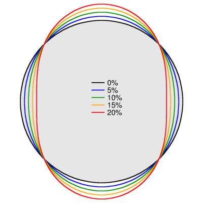
To model an eccentric chainring, I need to pick a shape. For simplicity, I assume the radius has a cosine-dependence on the angle, with two peaks and two valleys around the chainring circle. The radius of the amplitude of this cosine to the mean radius of the chainring I define as the "eccentricity". An eccentricity of 0 defines a circular chainring, while an eccentricity of 10% defines a ring where the effective number of teeth varies from 10% below to 10% above the number of teeth in a ring with the same mean radius. So a round ring with 50 teeth would be roughly comparable to a ring with 10% eccentricity where the instantaneous gear ratio varied from an effective 45 tooth front to a 55 tooth front, approximately.
Here's a comparison of chainring shapes with eccentricities of 0%, 5%, 10%, 15%, and 20%. 20% is fairly extreme, clearly: the front derailleur would face a substantial challenge with such an eccentric ring.
In contrast, here's Tour de France winner Chris Froome's rings, which are clearly eccentric, but not as extreme as my 20% case. According to Osymmetric, their commercially available big-ring corresponds to an eccentricity of 7%. I think Froome's rings are custom, however.

Chris Froome's rings (CyclingNews)
I'll look at the power-versus-rpm contours for the pedaling simulation, taking only the ninth full pedal stroke. Here's the result for a flat road with a rider going 80 rpm:

With round rings, the cadence is fairly constant: the inertia of the bike carries the feet through the dead spots. But the effect of the eccentric rings is profound. With the largest radius roughly aligned with the positions of maximum power application, the cadence drops to a minimum when power is at a maximum. The rings are working as designed. But it's clear there's now a strong correlation between cadence and power. There's also a correlation between cadence and torque (not plotted).
Now I consider a second case: where the rider is grinding up a 20% grade at 50 rpm. Here's that result:
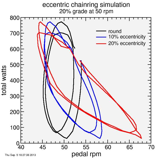
There's now considerable cadence variation through the pedal stroke with the round rings, but for each power, there's a high and low value with roughly the same average. The linear correlation is thus relatively small. With the eccentric rings, the shapes becomes more diagonal. The correlation is much stronger.
This negative linear correlation results in an overestimation of power, as was shown in the equations. Here's an example, pedaling on level ground accelerating from 40 rpm to 120 rpm with a 20% eccentric chainring. Note the rider only gets to 97 rpm during these pedal strokes.
nrot secs dt    avgrpm avgwatts avgtorque avgwattsCC err  ferr
0    1.26 1.26  47.5   453      10.1      482        28.5 0.0629
1    2.28 1.02  59     419      7.68      453        34.3 0.082
2    3.18 0.901 66.6   411      6.74      448        37.5 0.0913
3    4    0.822 72.7   458      6.85      498        40   0.0874
4    4.77 0.775 77.4   422      5.93      459        37.7 0.0895
5    5.51 0.737 81.3   413      5.56      452        39.7 0.0963
6    6.21 0.703 85     458      5.87      499        41.1 0.0896
7    6.9  0.682 88     422      5.23      461        38.5 0.0913
8    7.56 0.662 90.6   413      5.01      454        40.7 0.0984
9    8.2  0.642 93.2   458      5.37      500        41.4 0.0902
10   8.83 0.63  95.3   422      4.84      461        38.7 0.0917
11   9.45 0.617 97.1   414      4.68      455        41.2 0.0997
Note torque is nonstandard units here. The power is overestimated consistently, only 6.3% the first pedal stroke, but increasing to 10% the last pedal stroke of the 12.
Here's the root mean square error versus eccentricity for this case and two others. In each case the power is generally overestimated (although root mean square doesn't indicate if the error is positive or negative). The more eccentric the chainring, the worse the error:
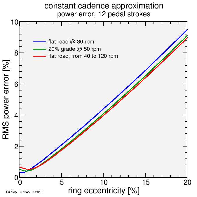
The conclusion here is the constant cadence approximation simply doesn't work for eccentric chainrings. It's possible to make some other, chainring-specific approximation which will allow for better results. But then if the user switches back to round rings the power would be underestimated. Better is to sample cadence on a detailed basis around the pedal stroke, then chainring shape shouldn't matter. Power2Max claims to do this. Perhaps Rotor does, since one hopes they work with their own eccentric chainrings, although they may simply have a different calibration setting for their rings. I'm not sure of any other.


Comments
What is the value of the powermeter when it does not provide you with the correct power-output? In other words, why is Froome using a SRM and O'symetrics?
Furthermore, could the use of O'symetrics seem beneficial due to the wrong (higher) outputs on an SRM? Meaning that people are tricked in believing they actually increased their power output? And the other way around, has Wiggo suffered in his power-output due to changing back to circular chainrings (while actually producing the same power outputs)?
Thanks for the blog, I love it!
You mentioned that inertia could assist the rider in overcoming the dead spot on a round ring during normal use. I would think that cadence will slow during that dead spot. This effect would be most noticeable when climbing. On the other hand, eccentric chainrings could reduce the dead spot and potentially lead to a more constant cadence.
Second, do you have any idea what the sampling rates of most PMs are? I think that Rotor published 500hz for theirs, but I haven't seen any numbers for the others. If (I don't know if this is true) the cadence is sampled at the same rate then it could be assumed that cadence is constant over 1/500th of a second. On DCRainmaker I posted that 1/500th of a second translates to 1.2° of rotation at 100rpm (which I normally ride close to that).
My wonder is if the Vector sampling rate is closer to the 1Hz that the Garmin head units acquire data at. Therefore a person could easily do more than one full rotation of the pedals.
Another interesting topic would be the time averaged data using eccentric chainrings. Would you expect the 3s/5s averaged data to be equivalent for eccentric rings?
On the sampling side: they sample torque at a high rate, but my blog post was dealing with cadence only, and that's often measured with a magnet (Quarq, SRM). I don't know about Rotor. Measuring cadence at a true 500 Hz would be very challenging. It would likely get filtered down to a more manageable bandwidth. Do you know the method Rotor uses?
Vector is event driven, so it reports power for each pedal stroke however long that takes. There's then some funny business to convert that into 1-second samples. There's way to do this which are better for real-time display, and ways which work better for archiving. I think it's only recently Garmin's head unit have started using a specific method for data archiving.
Anyway, I obviously find this stuff interesting, and I hope the Vector succeeds so they can extend its functionality during the next few years.