Vector and Stages power comparison
The last time I compared DC Rainmaker's total power numbers from Vector, Powertap, and Quarq on a typical ride near DC (Zip file here). The result was excellent agreement by my standards, considering the meters are measuring different points in the power transmission path.
 That leaves the Stages, which he also used. The Stages is not a total power meter; it's a left-leg power meter. It produces a derived number for total power by doubling left-leg power, but if you even glance at any Vector data, you realize that left leg and right leg power differ. Vector is also not a total power meter: it's two power meters. It's a left-leg meter and it's a right leg meter. These are distinct and are calibrated separately. You can derive total power by adding the two together, and the assumption here is total power is the sum of the left leg power and the right leg power. This is an excellent assumption as long as I'm not pushing with my hand on the crank arm.
So comparing Stages total power to the total power from another power meter is rather indirect. A better comparison is to compare Stages left leg power to the left leg power from another power meter. The obvious candidate is the Garmin Vector.
Additionally, I compared Stages left leg power to the Garmin's right leg power. This accomplishes two things. One is it checks to make sure there's any advantage to measuring power on both sides (if left leg power predicts right leg power, perhaps with a small offset but it still tracks) then we should see a narrow spread in this latter comparison and there's little advantage to be gained in using two sides, other than balance. But it also checks to make sure I'm labeling the Garmin powers correctly: if the Stages power were to be a better predictor of the Garmin R power han the Garmin L power, that would lend suspicion I had them swapped.
Here's the results, remembering I divided the Stages total power by two to get a Stages L-power (which is what it actually measured):
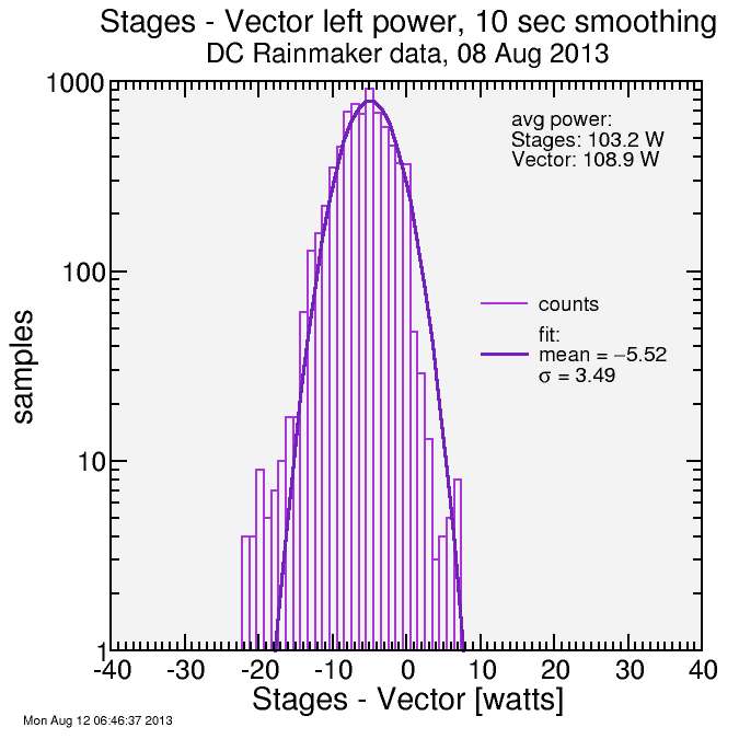
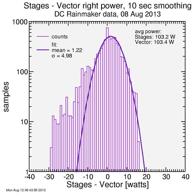
This is interesting: what is observed is that the average power from the Stages is a better match to the Garmin right power than the Garmin left power. This may in itself yield suspicion the Garmin powers were swapped. But looking at the spread of values makes it clear that Stages tracks the Garmin L power better than it tracks the Garmin R power. It suggests the agreement of the average value with the Garmin R power is fortuitous. Note in considering these σ values that they are from an average power roughly half that considered when looking at total power: the percentages are thus roughly double.
So the conclusion here is the comparison of left leg power from Stages to Garmin left leg power yields a decent amount of spread: 3.5 watts as calculated here. But comparing the Stages L power with the Garmin R power yields considerably more spread: 5.0 W with considerably more outliers.
The question is why is there such a big difference between the Stages L power and the Garmin L power: 5.5 watts. First I need to assess which is more trustworthy. The Garmin total power has already been compare with the total power from Quarq and Powertap (last post) and they tracked quite well. Since total power is derived from L and R power, the errors in L and R power must be even less then the errors in total power (there's no mechanism for errors to cancel between L and R). So this lends confidence to the Garmin numbers for both L power and R power.
I don't know, but I think what Stages is doing, measuring crank flex along the longer of two cross-sectional axes using an externally applied sensor, is challenging. Garmin is measuring the deflection of a hollow cylinder from the inside. That seems much more robust. Think about an eccentric beam with a major axis and a minor axis. It bends much more easily on its minor axis. Then I apply force from off-axis, attempting to bend it along the direction of the major axis (propulsive force). But I'm additionally providing a moment which is trying to bend it outward. since my foot is applying force outside the rotational plane of the crank arm. It's thus going to bend outward, along the minor axis, as well as along the major axis. Stages needs to measure only the bending along the major axis without being affected by bending along the minor axis. And, since I'm pushing forward on the axle, there's additionally a twisting moment. It just seems like a hard problem to me, and when I saw how well it seemed to work, I was impressed. But if it didn't work as well as a Quarq or SRM, which is measuring the wind-up stress in a spider, or as a Garmin, measuring the simple bending of a hollow cylinder, that wouldn't surprise me. But I'm not a mechanical engineer, so am no expert on these things. Still, it doesn't surprise me too much the left power doesn't agree closer than it does.
Despite my claim all that matters is single-pedal power when comparing to Stages, I at the last minute decided to run the "full power" numbers as well. Here's the result. The comparison isn't good, and this is with DC Rainmaker's relatively balanced L-R pedal stroke:
I just got out for my first outdoor ride since my crash 8 weeks ago, so it would be fun to give Vector a spin to see if my right-leg-injury translates to left-leg-dominance. These things are selling like hotcakes, though, so I may need to wait.


Comments
The vector also has 6 degrees of freedom to solve as well. The equations are different though for a beam vs. a cylinder.
Here is a good link to explain the beam equations a bit more:
http://en.wikipedia.org/wiki/Euler%E2%80%93Bernoulli_beam_theory
This makes the 2D problem for SRM/Quarq seem very simple.
Eitherway, i dont think the shape and the deflection/strain relationship are difficult engineering issues to solve. I think the difficulty is implementing the solution and making it accurate and reliable. From a theoretical standpoint, its a fairly straight forward problem to solve.
clipping path service
deep etching
photo manipulation service